Fire Prevention Week
I missed my regular Fire Prevention Week posts. So here we are, a little late...

Empower Young Women: Join POISED to Prosper!
I absolutely must share this with everyone who has a young woman in their life....

ASPE- Goldilocks and the Plumber
Here is an old ASPE article about Goldilocks and the Plumber that we turned into...

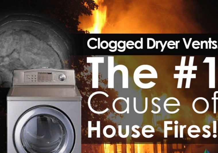
Duct Protection: Advance Construction Quality
If you are involved in multifamily residential, how do you protect the kitchen and dryer...
Floor Ceiling Assemblies vs. Concrete: Key Firestop Differences
Our last build better crew had some great discussions. We went over some of the...

Advance Construction Quality Conference
Im at a conference and the hotels were booked up so I got a Vrbo...

Does Your Community Need: Tools & Tiaras in aviation?
Does your community need Tools & Tiaras in aviation? Do you have an idea of...